
For: Operators, dealer layout and design teams, and installers planning or re-planning a commercial strength floor.
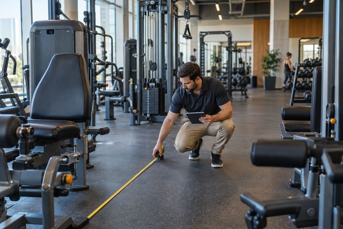
The decision: How many loaded stations a strength area can hold, and where each one goes, using each model’s published live area, the accessible route and your own peak-hour observations instead of a machine count.
60-second answer: Catalog dimensions describe the frame, not the floor it uses. As published by Life Fitness, the Hammer Strength HD Elite iD Power Rack measures 64 x 73 in with a 10 x 10 ft live area, and the Insignia Series Chest Press measures 43.2 x 55.3 in with a 67.2 x 55.3 in live area. Draw every model’s live area for the configuration being bought, lay the accessible route and the required 30 x 48 in clear floor spaces over the plan, and get a written live area for any model whose documents do not give one. Then test the drawing against counts taken at your own peak.
Footprint and live area are different numbers
A floor of well-chosen strength equipment for gyms can still crowd if the plan was drawn from frame dimensions. Some manufacturers publish a second figure for the space a machine uses in operation. As published by the manufacturer (accessed October 8, 2026):
- Hammer Strength HD Elite iD Power Rack (ELT-PR-STRD): 64 x 73 x 96 in, with a 10 x 10 ft live area. The frame covers about 32 sq ft; the live area is 100 sq ft.
- Hammer Strength HD Elite iD Half Rack (ELT-HR-STRD): 56 x 73 x 96 in, with a 7 x 10 ft live area.
- Life Fitness Insignia Series Chest Press (SS-CP): 43.2 x 55.3 x 58.1 in, with a live area of 67.2 x 55.3 x 82.7 in.
- Cybex Ion Series Leg Curl (CI-LC): the 2021 assembly instructions list 65 x 43 x 53 in and a live area of 101 x 67 x 77 in.
The allowance differs by model, so no single spacing rule carries across a floor. Life Fitness’s rack manual lists live areas without defining them; ask whether a figure covers loading, plate changes and a spotter. Some manuals add a separate access allowance: the owner’s manual for the Cybex Plate Loaded Incline Press (model 16195, revision B, 2015) calls for a “free area for access to unit and emergency dismount” with a minimum clearance of 23.6 in (0.6 m), says adjacent units may share it, and states that the dimensions in its assembly instructions include the maximum in-use footprint. Where a model’s product page, spec sheet and manual give no live area, get one in writing before the layout is approved.
Public standards summaries do not supply the number either. ASTM’s published scope and abstract for F2276-23, the general fitness equipment specification, cover design, manufacture and the instructions a manufacturer must supply; ISO’s published scope for ISO 20957-1:2024 covers general safety requirements and test methods for indoor stationary training equipment. Neither public summary states a floor-space figure. FEX has not reviewed the full texts, so ask the manufacturer which requirements its clearance figures implement.
Lay the routes and accessible spaces before the stations
Place stations after the routes, not before. Under the 2010 ADA Standards, exercise machines and equipment required to comply must be on an accessible route (section 206.2.13). The U.S. Access Board’s guide sets out the rest:
- At least one of each type of exercise machine or equipment needs clear floor space of at least 30 by 48 in, served by an accessible route. The guide says “most strength training equipment and machines would be considered different types.”
- The space must be positioned for transfer from a wheelchair or for use while seated; for a shoulder press it sits next to the seat.
- Clear floor spaces for more than one piece may overlap. A space enclosed on three sides, by walls or by the equipment itself, must be at least 36 by 48 in.
- Accessible routes need 36 in of continuous clear width, reducible to 32 in for no more than 24 in. A 180-degree turn around an element less than 48 in wide needs 48 in at the turn and 42 in approaching it, unless the turn is 60 in wide. Protruding objects cannot reduce the minimum, which on a strength floor includes bar ends and storage horns that reach into the route.
These are element minimums, not a whole-facility compliance finding, and existing buildings need project-specific review. Egress falls under the building and fire codes adopted locally; the design professional and code official decide it. The drawing method is in planning clear floor space and routes together.
Test the drawing against your own peak
Test the plan against your own records, not a typical utilization figure.
Records to pull: the current dimensioned plan with its revision date; an equipment schedule with model numbers and configurations; the spec sheet or manual each live area came from; check-in or access data by hour, to identify your peak; the class and personal-training timetable for the area; and incident or near-miss reports that mention the strength floor.
Observe: during the peak hours your data identifies, count occupied stations at intervals you fix in advance, and mark where people stand while waiting, where plates and bars are set down, and where walking routes cross a live area. From the positions staff actually stand in, note which stations they cannot see. Photograph the floor at close on the same days, and repeat over enough sessions to cover the programs that use the room.
Map movements to stations: list the movements your programs schedule and the stations that serve each one. Gaps and duplicates show where a different model, or a smaller live area, would serve the floor better than another unit.
Waiting at the station with routes clear points to a capacity question. Waiting off to one side, identical units used unevenly, or plates parked in a route point to the layout. The diagnostic method is in reading congestion from where people stand.
| Check | Where the answer comes from | Plan is ready | Plan needs work |
|---|---|---|---|
| Live area for each model | Product page, spec sheet or manual, with revision noted | Drawn for the configuration being bought | Frame dimensions only, or one allowance applied to every model |
| Overlap between stations | Manufacturer’s documents | Shared only where the documents allow it | Live areas overlap with no written basis |
| Accessible route | 2010 ADA Standards and Access Board guide | 36 in clear and continuous, including at turns | Narrowed by bar ends, storage or a bench |
| Clear floor space by type | Equipment schedule and plan | 30 x 48 in (36 x 48 in where enclosed on three sides) at one of each type, on the route | Missing, or occupied by storage |
| Walking routes | Plan and peak observation | No route crosses a live area | Members cut through loading space |
| Plate and accessory storage | Plan and close-of-day photos | Inside the zone it serves, outside live areas and routes | Items left on the floor at close |
| Anchoring and flooring | Rack manual and flooring documents | Requirement confirmed for the configuration | “Optional,” with no written basis |
| Document control | Plan title block | Every figure traceable to a dated document | Figures from memory or another model’s sheet |
Questions, triggers and red flags
Ask the supplier, in writing: the live area for the exact model and configuration, and its source document; what it includes; whether adjacent units may share it; whether storage options or attachments change it; whether the configuration must be anchored, and through how much flooring; and assembled and boxed weights. For racks the anchoring answer is model- and configuration-specific; see setting the rack anchoring scope.
Triggers you set: re-check the plan whenever a model is substituted, a configuration or storage option changes, a station moves, a new program is scheduled into the area, or your observations show a route crossing a live area. Record each re-check against the plan revision.
Red flags: a layout drawn from catalog dimensions; one spacing allowance used for every model; clear floor spaces that hold plate trees by the end of the week; live areas overlapping the main walking route; and a plan with no document references.
What to do this week
- List every strength model on the floor with its configuration and the document that gives its live area, and request the missing ones.
- Redraw the plan with live areas, the accessible route and one 30 x 48 in clear floor space (36 x 48 in where enclosed on three sides) per equipment type.
- Mark every point where a walking route or storage crosses a live area.
- Pull check-in data to fix your peak hours, then count stations and mark wait positions on a printed plan during them.
- Resolve route and storage conflicts before pricing additional stations.
Continue with FEX
- Size a room from clearances, not a machine count
- Floor load capacity for upper-level rooms
- Pilot footprint and workflow before a fleet order
FEX editorial guidance: the plan check, observation method and movement mapping are FEX analysis. Dimensions and live areas are as published by the manufacturer for the named models and configurations (accessed October 8, 2026) and do not carry over to other models. ADA figures come from the 2010 ADA Standards and the U.S. Access Board’s guide. This is not legal, accessibility or engineering advice; confirm applicability with the design professional, an accessibility consultant and the code official. Manufacturer instructions control installation.
Source notes
- Life Fitness: HD Elite iD Power Rack (accessed October 8, 2026) — Product code, dimensions and 10 x 10 ft live area.
- Life Fitness: HD Elite iD Half Rack (accessed October 8, 2026) — Product code, dimensions and 7 x 10 ft live area.
- Life Fitness: Hammer Strength HD Elite iD Racks Owner’s Manual, 1022942-0001 rev. AD (2025; accessed October 8, 2026) — Live areas listed by model without a definition; configuration-specific anchoring.
- Life Fitness: Insignia Series Chest Press (accessed October 8, 2026) — Product code, dimensions and live area.
- Cybex: Ion Series Leg Curl Assembly Instructions, 1017120-0001 AA (2021; accessed October 8, 2026) — Size and live area.
- Cybex: Plate Loaded Incline Press Owner’s Manual, 16195-999-4 rev. B (June 2015; accessed October 8, 2026) — 23.6 in (0.6 m) free area, shared free area, dimensions including in-use footprint.
- ASTM International: F2276-23 Standard Specification for Fitness Equipment (page last updated September 12, 2023; accessed October 8, 2026) — Published scope and abstract.
- ISO: ISO 20957-1:2024 (published November 2024; accessed October 8, 2026) — Published scope.
- U.S. Access Board: 2010 ADA Standards (accessed October 8, 2026) — Section 206.2.13, exercise equipment on an accessible route.
- U.S. Access Board: Guide to the ADA Standards, Chapter 10: Sports Facilities (accessed October 8, 2026) — One of each type, 30 x 48 in clear floor space, positioning, overlap, 36 x 48 in where enclosed on three sides.
- U.S. Access Board: Guide to the ADA Standards, Chapter 4: Accessible Routes (accessed October 8, 2026) — Route widths, turns and protruding objects.
Editorial update, October 8, 2026: Removed the unsourced nine-pattern rule, sightline and change-zone thresholds and the claim about how often failures appear; replaced them with live areas published by Life Fitness and Cybex for named models, ADA route and clear floor space rules verified with the U.S. Access Board, and an observation method based on the operator’s own records.